Charles Drown Mower’s 1898 Racing Dory for the Swampscott Club
THE PLANS
Unexpected things happen, sometimes out of the blue and sometimes from right under one’s nose.
20 years or so ago David Clark (Englishman, Marblehead contractor) came to my shop in Marblehead saying there was a boat shop up at Fort Sewell that was being turned into a playhouse, the museums and antique dealers had been through it, and there was still boat stuff in it. Everything was going to the dump and I should go and take anything I wanted.
This was the boat shop of Bill and Sam Brown. Of course I went, towing my trailer. There were some old drawers with mostly broken or partial boat parts. There were the steam boxes and the wood fired candy stove that fired the boiler. There was the planking bench whose parts I took, AND there was this tight roll of “paper” up in the eaves over the planking bench. This last was exciting, but I had to load and unload what I could save ahead of David’s workers before I could study this find.
The “paper” turned out to be drafting linen, three sheets, with Mower’s pencil drawings from 1898 (the lines dated Dec. 16, the construction dated Dec. 18) and 1899 (sail plan dated Mar. 14). Mower was from Winthrop, had built himself a “successful” boat, and had been worked as draftsman for Arthur Binney and then B. B. Crowninshield when he got this commission. In the Summer of 1899 he took the job of design editor at The Rudder and moved to NY. In 1911 Mower updated the 21′ dory, this time for broadly described Massachusetts Bay not just for the Swampscott Club, this time a decked boat — the earlier boats are reported to have had decks added after the first season.
I found that the Swampscott Club still existed and took the drawings to show the group there, but this was now a social club across the street from the water. They knew some of the club’s sailing history with these dories, but were not much interested. They called it the X Dory and said they got decked early on. This has been substantiated in Matt Murphy’s book of Willard Jackson photographs, GLASS PLATES AND WOODEN BOATS, pages 36-37 with the 1907 image of SUNNY JIM and pages 68-69 picturing X-Dory Start from 1903.
I took the drawings to Mystic Seaport Museum, showing them to Peter Vermilya, Small Craft Curator, who with Plans Department staff made copies of the drawings, one for the Seaport collection. Peter’s first comment was to the effect that I had to build this boat. I also got from the Seaport library a copy of the Feb. 1900 article about the boats and the design, almost certainly written by Mower though unsigned. I also gave a copy to the Peabody Museum in Salem, MA, holders of Sam Brown’s design collection.
This design is important as C. D. Mower’s first commissioned design, the first of a long career in which he designed many beautiful and otherwise noteworthy vessels. This design came at the beginning of an era of 21’ dory racing with clubs like the Beachcomber in Marblehead and the Alpha in Salem, as well as the club in Swampscott, and this design itself is simply beautiful. I had the drawings matted and framed to hang on the wall.
Why was the Mower Drawing in the Brown shop? I knew Sam had designed the Yankee Dory, a later 18’er, and I thought that might have been a particular point of interest. Then, discussing the Mower I was asked about it’s relationship to the Chamberlain gunning dory, a double ended rowing boat, and I got out John Gardner’s article about the Chamberlain Beachcomber, another 21‘ racing dory designed in 1898. Gardner says,
“Chamberlain built superior dories, and won races and cups sailing them. Yet when the Beachcomber Dory Club was formed on the Marblehead waterfront sometime in the 1890s, Chamberlain may not have been sole builder of club dories. There is evidence that, at first, members’ boats and rigs were far from being uniform. But evidently Chamberlain’s model soon became standard and had no competition until about 1912 when a young dory sailor by the name of Sam Brown, later to become a successful naval architect, designed the Outlaw for Ed Murphy.”
Gardner goes on to talk about Ben Tutt saying Outlaw was responsible for breaking up the Beachcomber Club, although it did carry on into the 30’s with design changes aimed at competing with the Outlaw. Gardner doesn’t talk in great detail, but the details mentioned — flatter sheer, broader, heavier, etc. — sounded more like the Mower design than Chamberlain’s. Contacting Dan Finamore at the Peabody-Essex Museum in Salem I found they have the Outlaw drawings and arranged to look at them.
Placing the Outlaw body plan between the Beachcomber and the 1898 Mower, it seems very likely that Sam Brown worked from the Mower in working up his design. The Beachcombers being narrower with a smaller sail plan, Sam Brown’s garboard is narrower, but the deadrise is about 20 degrees, to Chamberlain’s 30 and Mower’s 16. Then the Beachcomber plank line is nearly straight to the chine below the second plank down, while Brown has a wider garboard on that lower line to distinct chines below each of the three topside planks. Outlaw’s stem also has more of the extension seen in Mower’s design, fairing into the line of the bottom where Chamberlain’s stem takes an angle up from the bottom and is shorter.
So (again), now I think Sam Brown had these drawings in 1912 when he built the Outlaw and that’s why they were in the shop. Black on the edge from soot and time, and covered with dust, they might well have been untouched since 1912, lying under the eaves waiting for me just as Gardner’s information was waiting on my book shelf.
When C. D. Mower drew updated plans of the racing dory for Massachusetts Bay in 1911 he made some changes that seem to make it easier for the builder and might encourage building the boat, included scantlings and offsets missing entirely from the earlier plan, and included a deck slightly different from the decks that had been added to the earlier boats. He also drew a narrower bottom board with more rocker and added a plank, eliminating the earlier broad garboard, giving it a fuller round bottom. With deck for rigidity the only thwart left braces the centerboard trunk, this was a racing boat meant for class racing not for sitting around, designed to be built to rule widely, not just by the Swampscott builder given the contract for the earlier boat. In 1911, Mower was 36, not 23, but his earlier dory was still impressive enough for the Massachusetts Bay Racing Association to ask for updated plans. Boats built to the earlier design continued to race with the updated design boats all under the MBRA X-Class rule, they are that similar.
Carrying the development story further, when Lee Van Gemert saw the 1898 Mower drawings he said, that’s where the Indian came from. In 1921 members of the Massachusetts Bay Racing Association and the Eastern Yacht Club went to John Alden asking for a design based on the 1911 Mower dory, for their children. Sam Crocker working for Alden produced the Indian design. With her wide transom, skeg hung rudder and 30 foot mast, the Indian is a much more powerful boat. Too much boat for the kids, the original fleet of 6 built by Chamberlain in Marblehead were sold before the year was out to sailors from the south of Boston. The Indian became the largest sailing class in Massachusetts Bay, popular many other places as well.

All this is very interesting, but these drawing are beautiful and more importantly the boat is drawn beautifully. There are a few little black marks on the sheets where Mr. Mower rubbed his pencil lead back and forth to get a sharp point, a little personal detail. But, with the “update” of 1911, and lately only the small scale images in The Rudder available, I think it likely there have been none of these boats built for more than 100 years. Such an elegant design deserves recognition but even more it cries out to be sailed, which I finally mean to do.
BUILDING THE 1898 MOWER DORY
With no offsets given, they must be measured on the lines plan. Using the water line as the base line, instead of drawing my own baseline, heights are measured as positive and negative numbers. Typical of dory design, stations are set at frame positions, and it seemed clear by comparing the lines and construction drawings that the lines were drawn to the inside of the planks. The plans for the 1911 dory show measurements for all the backbone parts so lofting is not required, but I lofted, to fair the lines from my measurements and to take bevels off the lofting. Not having 21’ of floor I lofted on 14’ sections of rosin paper. From the lofting I expanded the transom to it’s full size, inside and out, overlaid on tracing paper, and took half breadth and length measurements for the bottom board, inside and out. I also made traced patterns for the frames and stem, with bevels shown.
Planing white oak stock to 1 7/8” for the stem and 7/8” for the frames, marks were made from the tracings and lines drawn. The frames were to be joined on the station lines so bevels were to be cut opposite for each side, bottom bevels cut to bring frames plumb off bottom board rocker, plank landings beveled to match the arc of the planks. With lines drawn on my stock it was off to a friends bandsaw to make the cuts. Bringing the pieces home I planed to my lines and riveted frame pairs together, making sure bottom board widths were on station and centerlines marked, plywood stretchers between frame tops secured sheer height and breadth.
All the above happened in the first half of 2012. Gall bladder surgery in February 2012 made plan and lofting good work during recovery time. Then sailing and outside work took over for much of the summer.
Working in an area with snowy cold winters I needed to make an improved building site. An artist friend of mine, in tribute to Native Americans, had made a “shadow” village of wigwams, bending saplings over with black net covering. Using the idea, I cut a bunch of ash saplings, stuck them in the ground 10’ apart, bent over and lashed them together in the middle. Lengthwise and diagonal saplings completed a structure woven and lashed together. Covered with shrinkwrap plastic this made winter building easy and dry when temperatures were above 20F. Planing and milling was still being done outside, but even with a snowy winter progress continued.
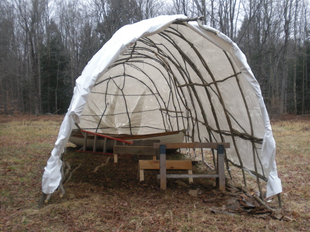
wigwam

Frame set up
A locust 6×8 was to be the strongback for building. With the narrow longhouse, I made low saw horses with hardwood cross pieces on top so I could slide the beam from side to side as work went from one side to the other. I was able to get pine boards with 2’ widths of heart wood, 15’ long for the bottom board and 4’ long for the transom. With the cutting of the stern knee, now it could start to go together.
Cutting the board for the bottom to length, centerline location was marked and squared across the ends, and lines snapped. The stations were squared off on both sides and the halfbreadths marked off from the center lines. With batten bent around these marks, the bottom outlines were drawn and the top outline cut to with the circular saw. The bevel between the top and bottom outlines was cut with power planer and hand planes. The joint between the bottom board and garboard will be a caulked joint and an oak false bottom will be installed between the lower garboard edges, in the mean time when the frames are fastened to the bottom board, bevel adjustments can be made if desired.
Clamping the frame sets to the bottom board, fit was checked and outlines drawn so fastener holes could be drilled from the top before final fitting and fastening with screws drilled for from below. After cutting limbers in the frames they were again clamped and then fastened on station. The stem was bolted to the front of the bottom board and the transom knee to the stern.
Lay out lines, center line and water line were needed on pattern and transom stock, squared across the stock to mark the proper bevels between front and back. With lines drawn the transom was cut out, planed to the lines, and bolted to it’s knee. The transom being pine and the plank landing being quite oblique, 1/2” thick oak nailers were screwed to the straight transom edges, to the top chine, where they were cut square to the centerline so a top cleat could be installed across the top — this was thicker, locust and beveled for the sheer strake landing.
With the building structure fastened to the bottom board it was ready for fastening to the strongback. With one long screw through a temporary cleat across the bottom board and the center of the bottom board just ahead of station 3, where the centerboard slot will be, the whole assembly was screwed to the locust timber. With the low point of the bottom down the ends could now be jacked up to give the bottom it’s required rocker. To complete setup for planking, boards were fastened from stem head to transom, fastened to frame cross pieces, to hold centerline alignment.

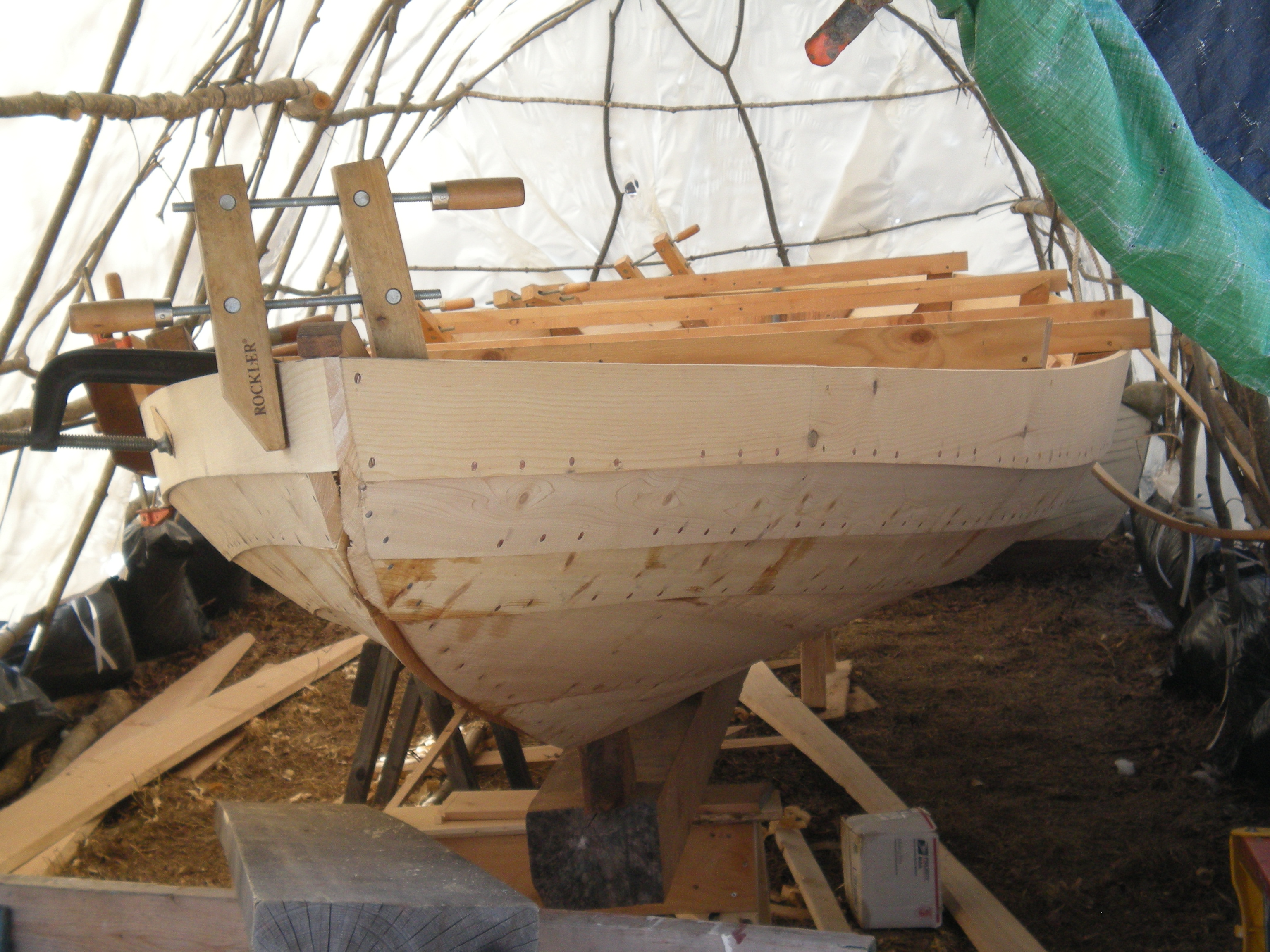
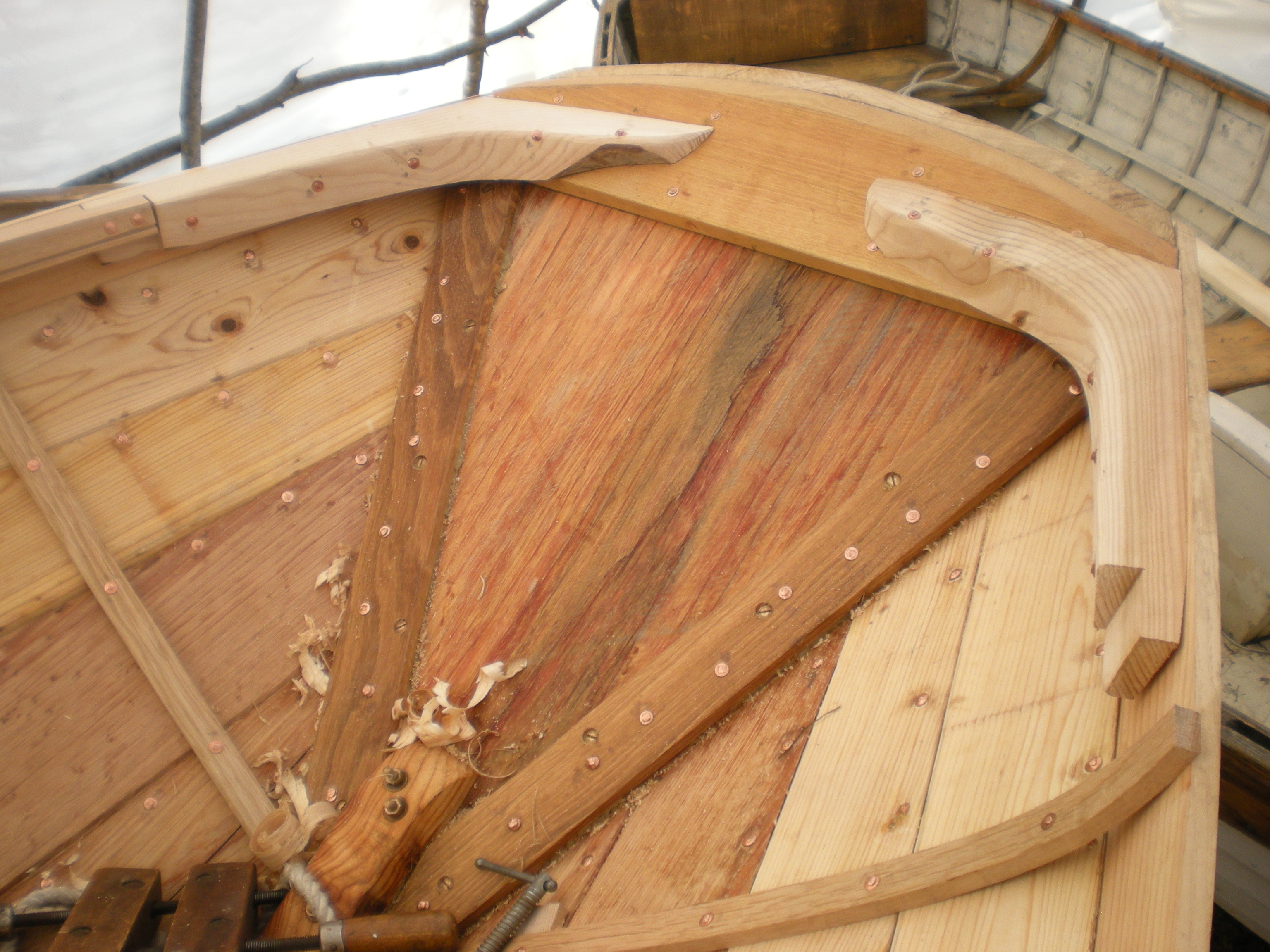
garboard and broad

garboard and broad interior
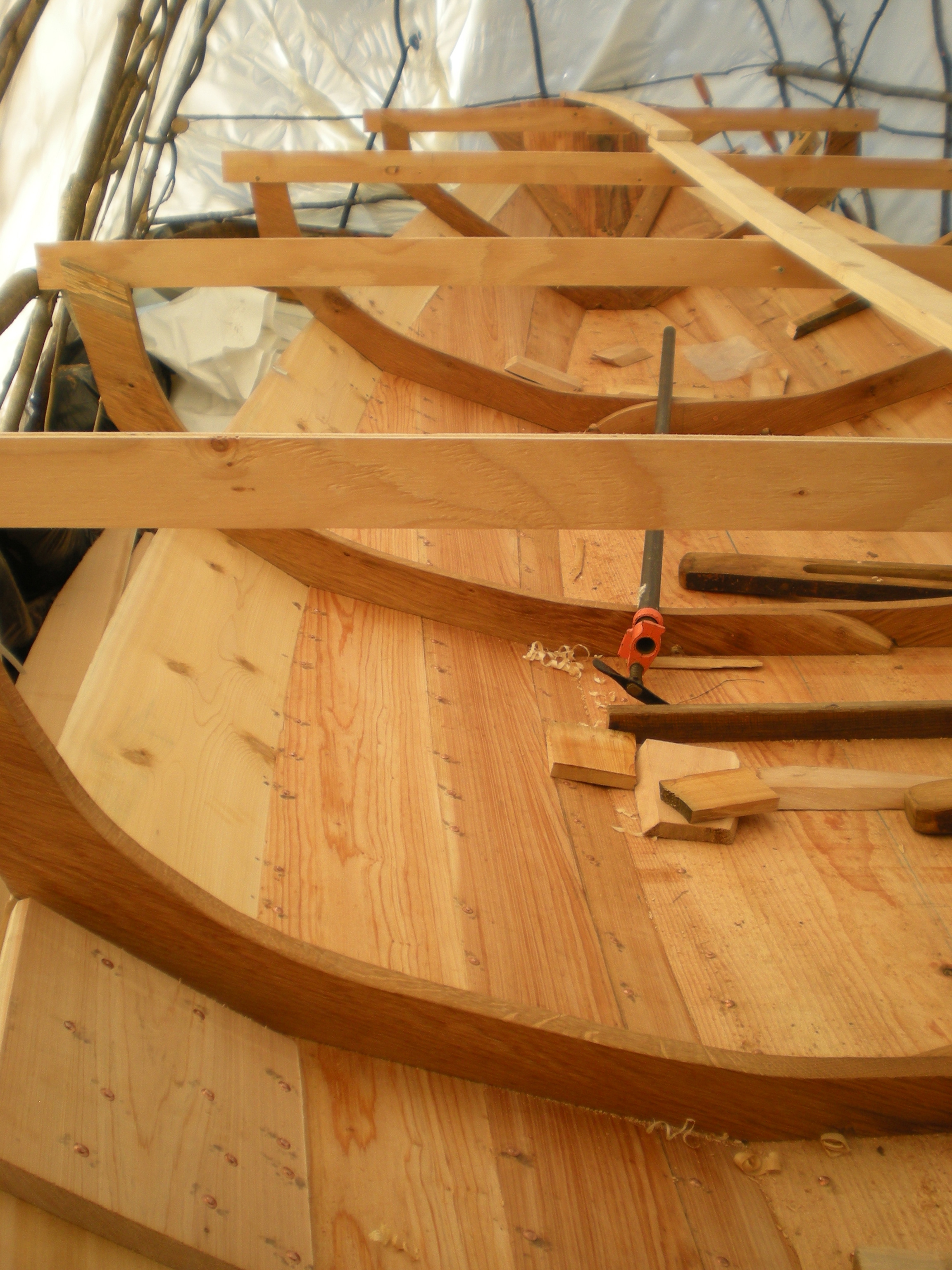
interior structure
Mower’s drawing shows a garboard 19” wide at station 3, spiling shows a lower edge with some 6” sweep, so you would need a board more than 2’ wide for a one piece garboard and one for each side. Plank stock like this might have been available in 1898, but maybe not so easily in 1911 and certainly not today. With a 12” wide plank and 6 inches of bevel under the top of the bottom board there is only 6” showing at the narrowest point of the plank. You might see the problem, and for strength with light planking and minimal structure the typical approach, and mine, is called dory lap. To make three boards serve as a single flat plank, the joining edges are cut on 45 degree angles and riveted. The lower edge of the garboard is cut square, the false bottom will protect these edges in the finished boat and this allows solid fastening between garboard and bottom board. A small pile of long and wide Atlantic white cedar boards hopefully would be enough for the garboards and were. 5/4, resawing might have left a little under 1/2” but without resaw capacity I was just as happy planing to 11/16 as a compromise between strength and lightness.
To spile for the garboard I planed down a 15’ knotty cedar board and bent it around the frames so I could trace the upper edge of the bottom board, mark frame positions and draw lines where it would pass the transom and the stem, measuring the width of the bottom board bevel to establish the lower garboard edge. Getting out a couple of likely boards, the shape of the lower edge was marked with nails through the spiling board and pencil marks for frames and ends, then a batten was bent around the marks and the line penciled. The upper edge of these planks would be cut at 45 degrees, and was made fair and as straight as the stock would allow. After cutting the plank out of the first board, lines were traced onto the second board. When both blanks were cut they could be planed to thickness keeping as much finished width as possible.
For fasteners I had monel ring nails and square shank copper nails for rivets, both gifts to me from other peoples long ago projects. I nailed the planks to the frames and stem, riveting planks to bottom board, transom, and plank joins between the frames. My basic plank fastening schedule was three inch spacings. The frame/station spacings are 3 feet, so I left 6 inch gaps in fastening every 12 inches where bent ribs will land and be fastened after planking was complete.
With the lower garboard planks fastened, the next planks are cut with the matching shape using the cut off for one of the lower planks. Again these boards were not wide enough to reach the first chine, so the shape at the chine had to be spiled and bent batten arc drawn from stem and transom marks as far as they would go. The top edge was then cut straight on the 45. Because of the differing shapes of these boards the final pieces of garboard, completely filling to the first chine, were different lengths, 14’ and 10’. When these pieces were fit, with a few minor adjustment, they were fastened.
The top edges at the chine below the first topside plank are 45s but with chine angle most of the way the lower edge of the next planks must be beveled to fit. With 11/16” plank thickness, the 45 degree bevel is just under 1” long, a good lap landing, but how to define the matching bevel was the question. My solution was to put a plank thickness block on each frame and with a straight edge measure the span beyond the end of the 45, these measurements varied between nothing at the transom with it’s straight line to the bottom of sheer plank to more than half plank thickness where chine angle was greatest. With spiling batten bent around the frames the chine at top of plank was marked as well as the width of the plank at transom, stem and frame.
With no more Atlantic White Cedar I went to Eastern/Maine White Cedar for the first two topside planks, using butt blocks as no boards were long enough for full length planks. I had Eastern White Pine with length and width, and considered using that but the sweep in the first plank was too much to get two planks out of one board, so I kept the pine for the sheer strakes, wanting them full length. Taking my marks and measurements from the spiling, the top and bottom for the plank on one side was marked at each station including one station past the planned butt joint on each board, lines were drawn against a bent batten. I cut square to all these lines because if I had cut the 45 degree bevel the width of the plank would change as the plank was planed and planing to the 45 would not be difficult. The pieces for the one side were used to pattern the second set. Marks and lines were drawn and drawn again so station locations on each plank were not lost in planing, planing to thickness, 11/16”, being done after the plank blanks were cut from the cedar boards.
sheerstrakes

planked side
transom
Plank thickness being 11/16”, drawing a line that distance into the plank face defined 45 degrees with the inner edge with the corner planed away. The lower edge joint was defined in the same way except lines were drawn along the lower edge for a rolling bevel as the bevel angle varied between 45 and less than half that. With a planking bench made up of saw horses and a spruce plank, bevels were planed with power planer, finished with hand planes. Clamping the planks in place I checked the fit, taking them off to make adjustments in widths and bevels. Deciding where to locate the butt joints, I cut one plank for the butt, marking the mate which was then cut and planed to fit, beveled for caulking. For butt blocks I used plank thickness cedar beveled on the lower edge to lap the plank below. Fastening was done as for the garboard planks with butt blocks riveted to butts and backing the lap. The second topside planks were similarly done with the butts placed between stations 3 and 4, instead of stations 1 and 2 as in the lower topside planks (Mower’s numbering and Brown’s too, station 1 being the first frame position on the bottom board, with the frame landing on the stem at station 0). I wanted a full length sheer strake, especially as I had the stock in a long and wide pine board with little sapwood. It was a near thing, but I was able to get both sides out of the one board. The chine angle to the sheer strake is 45 degrees at the stern and near flush at the bow, so the bevel on the inside lower edge of the planks went from nothing to the reciprocal 45, stern to bow. With adjustment and fastening done, and the ends trimmed off roughly as with the lower strakes, now I had to decide how to proceed. I still mulled building her with a deck. More and more I liked the original plan and think the deck connected to racing. That said, the bent ribs were still to come, allowing a bit more time to mull the final finish. Not a lot of time, a day milling out a bundle of 1” x 1/2” oak staves and, with a couple of helpers and steam up, a couple of hours steaming and bending was followed by riveting over a couple of days.

bent ribs

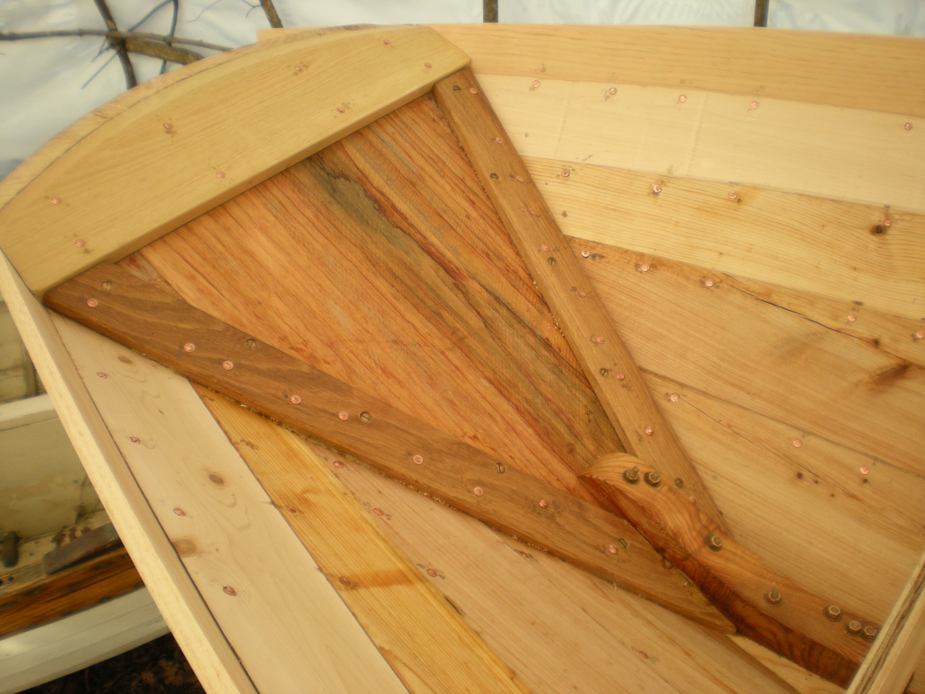
breasthook, inwale joint
quarter knees

rail structure
Next came breasthook and quarter knees, and decision time (knowing the original boats were built open and later decked over, nothing is lost). I tried one set of hackmatack knees, but then made patterns of the required shapes and found one knee from which I could cut all three with rabbets on the plank side arms for lap joints with the inwales.
My building set up was pretty basic, verging on primitive. In setting up the basic structure I relied on my lofted knee angles and the bending of the pine bottom to put the sheer at stem and transom at the desired height — stem to stern had measured exactly 21 feet, so I had been pretty sure I was close. With planking done I could see the sheer dropping at the ends, so before trimming the frames and ribs down below the line of the inwale bottom I bent a batten along the sheer to improve the look. With the line drawn to the batten I measured down the frames and ribs, squaring off the sheerstrake, drawing lines for cuts so the inwale would land on top and it’s top would be flush with the sheer. After removing the cross spalls from the frame ends, and sawing off frame and rib tops, inwales could be bent in and fastened.
I had a 6/4 oak plank for the inwales from which I got out two 1 3/8” x 1 11/16” pieces long enough for the 19+ feet needed. A routed bead on the lower inner edge of the inwales seemed like a nice touch as well as leaving a rounded edge. The upper edge just got a little relief. With the lap cut to join with the breasthook and the aft end supported, the piece was bent to the sheer strake, wide face on top. Bending thick stock like this is possible with air dry white oak, but it has to be done gradually. Starting with the half lap clamped to the breasthook, pulling and clamping at the next two frames, a hammer rap on the far end to tighten breasthook fit showed that a little adjustment of the joint fit was in order. Adjustment made, the piece clamped in place again, a little saw kerf made for a good fit. At this point the far end needed to be pulled in so I would be pulling toward me instead of pushing with the boat sliding away. Frame by frame the oak was clamped at each station until marks could be made for the half lap to the quarter knee. With the lap cut from the rail and all clamped, I worked back along the rail, trimming the frames and ribs to bring the oak flush with the sheer all along. Now it was ready for fastening, riveting through the half laps and with #12 x 1 1/2” silicon bronze wood screws on 12” centers between the ends. This process was repeated on the other side before oiling the topside strakes, ribs, knees and rails.

risers, ribs and centerboard slot
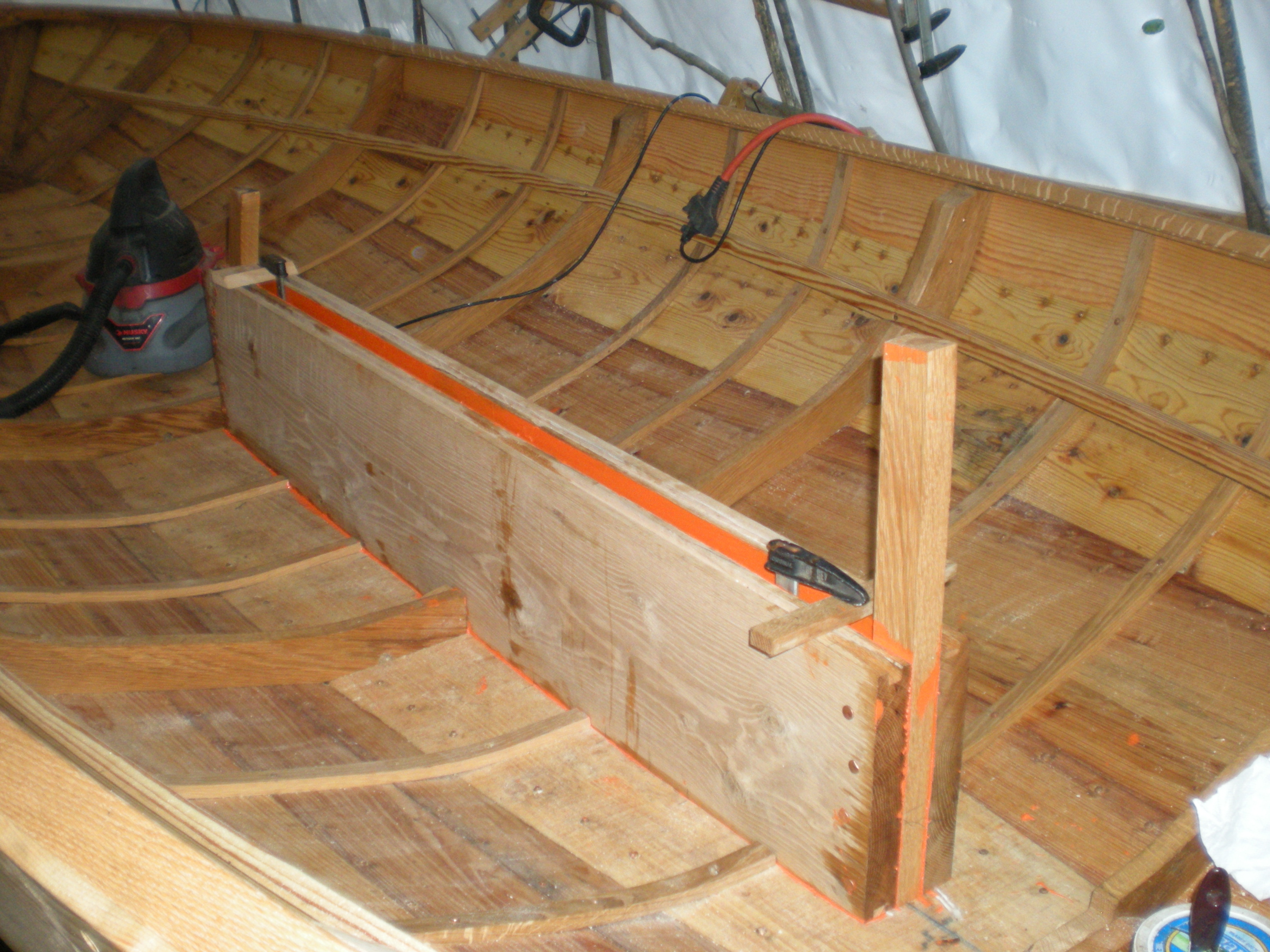
centerboard trunk logs installed
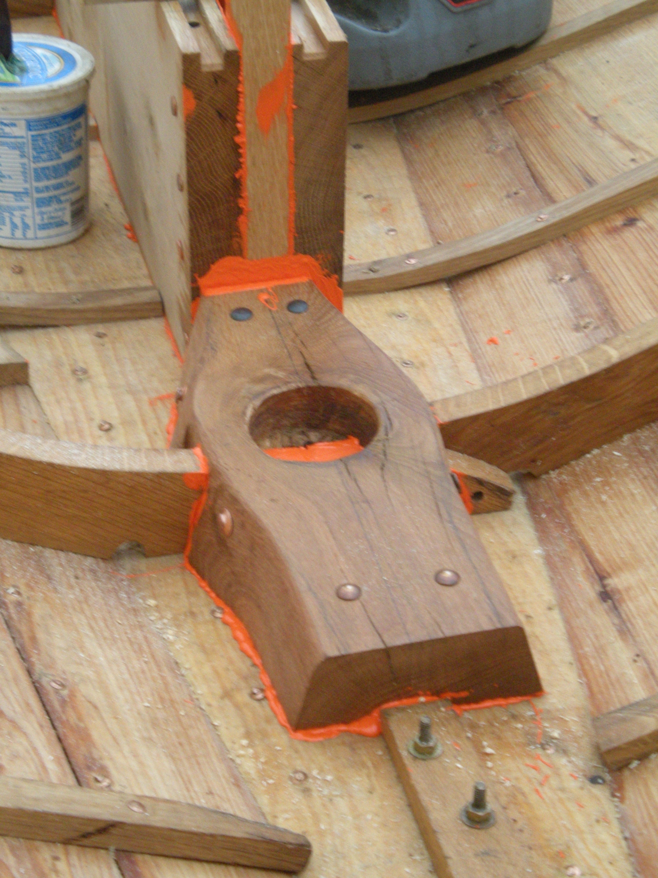
mast step
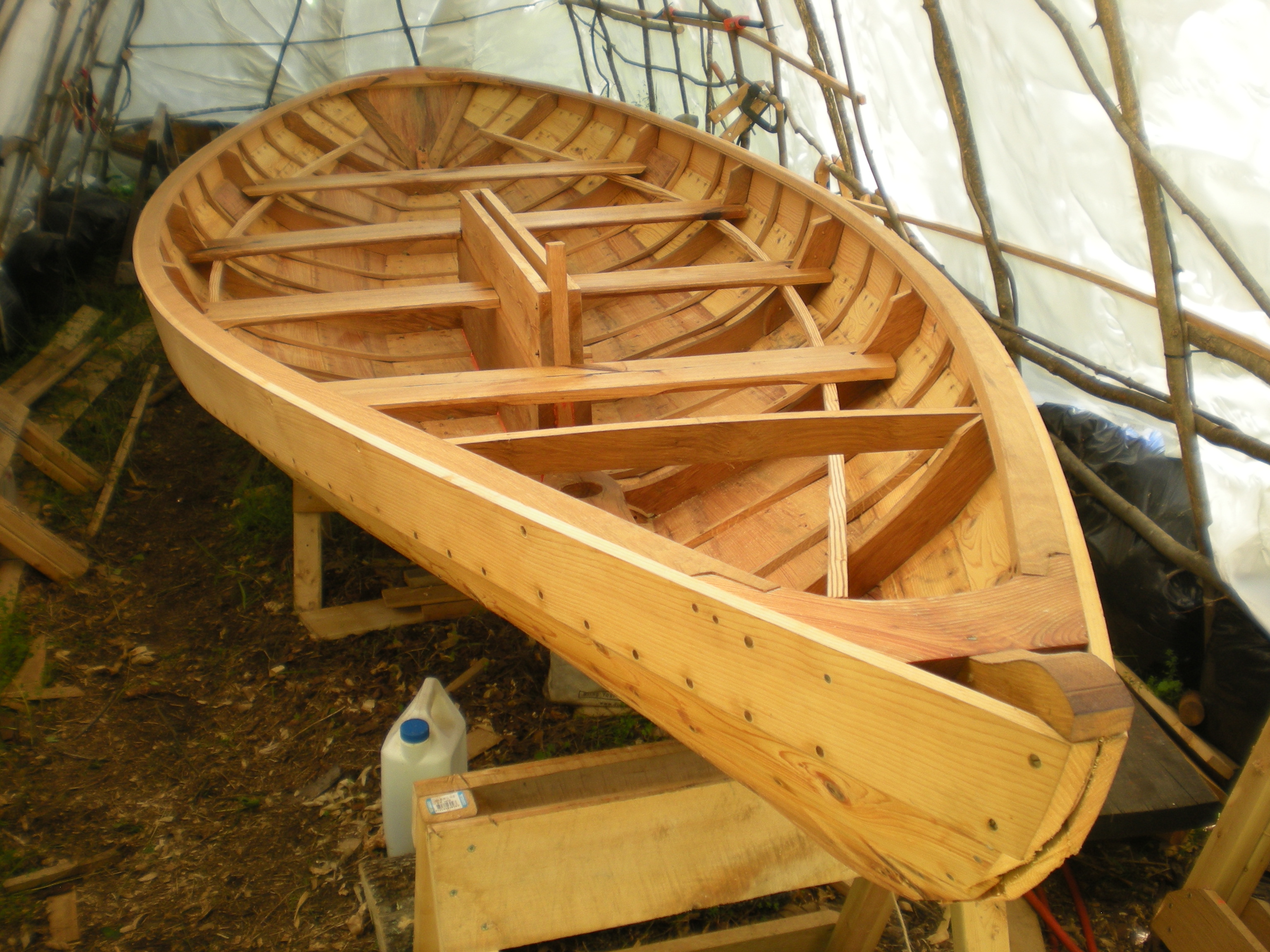
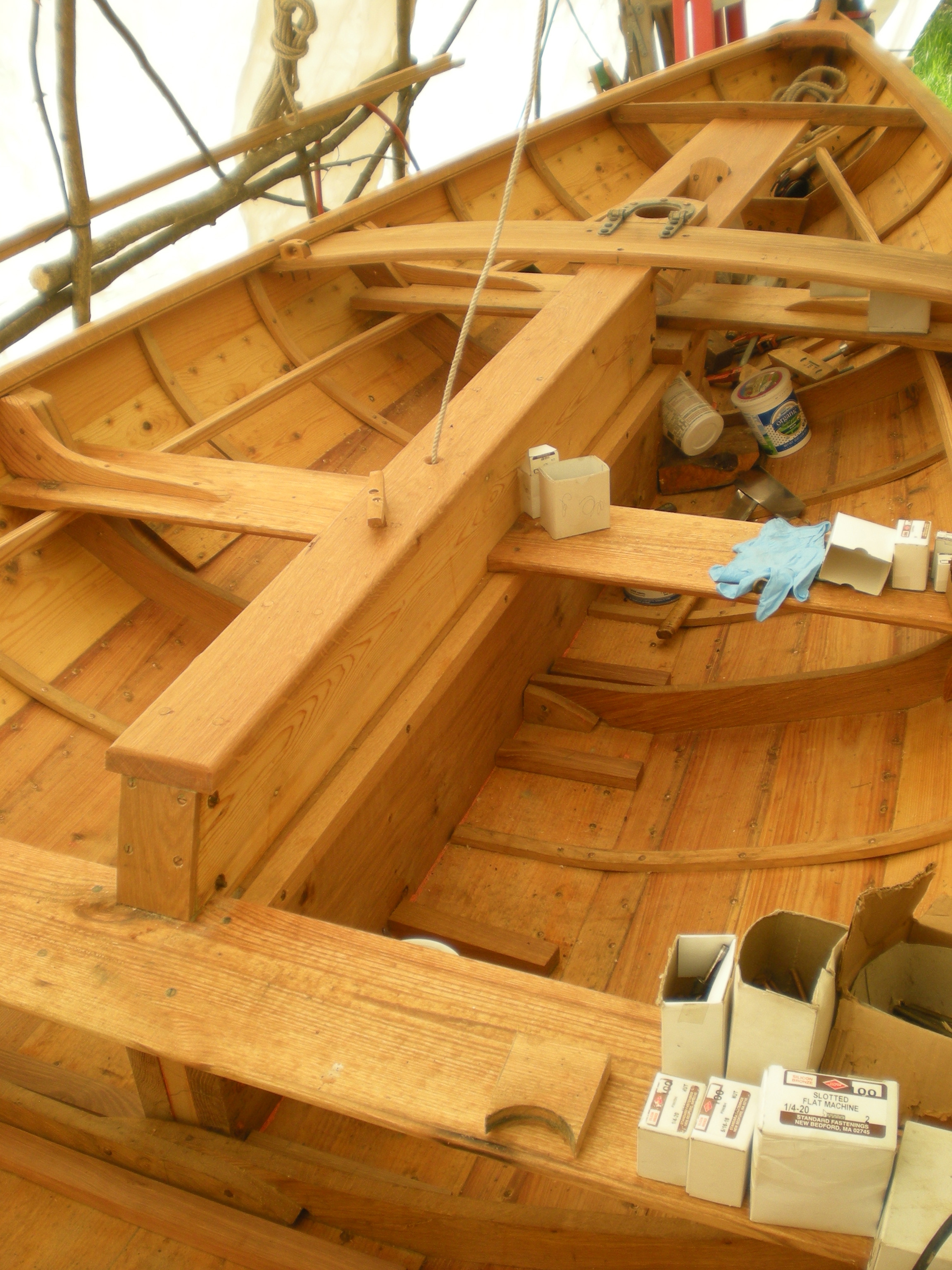
centerboard trunk and thwarts installed
For full rigidity and function the hull interior now needed risers, thwarts including mast partner, centerboard trunk and mast step. My approach started with the centerboard trunk. I was extending it further forward than Mower had it, and using a lower profile board, but Mower shows the thwarts at stations 2 and 3 landing on the trunk, crossing it at station 3. This is important for tying the trunk to the hull against the pressure on the upper corner of the lowered centerboard. I wanted heavy oak timber for the bottom sections of the trunk and meant to have the upper edge of those pieces at thwart level. Cutting away the centers of the ribs and frame #2, I spiled and patterned the bottom rocker forward of frame #3. Applying this arc to a couple of oak planks, I found that I could have 12 inches at frame #3 and 10 1/2” just aft of the mast step. Cutting and planing these pieces (ending up sided 6/4) and placing them in position I found their height just about right (based on my ideas and Mr. Mower’s drawing), so leveled across to locate riser positions on the frames.
When C. D. Mower updated this design in 1911 he redrew the centerboard and trunk. In 1898 he called for a board with a tall arcing top, higher than the sheer by 4 inches but only 10 inches above the bottom board at the forward end, so the leverage of the board in use was mostly taken by pressure on the #2 station thwarts. In updating the plan, Mower called for a rectangular board with top just below rail height. The Massachusetts Bay Indian has a longer rectangular board also just below rail height. Both the later designs are drawn as decked boats with the forward head ledge tied into the deck structure for good trunk support. I was not installing a deck, but I also know that even before decks were installed in the 1898 boats the mast partner was raised to rail level for better mast support, in the original drawings there are only 9 inches between the top of the mast step and the top of the mast partner holding up a 21 foot mast carrying 200 square feet of sail. Making the board and trunk longer, starting just aft of the mast step, I decided to go with a rectangular board and tie the head ledge to beams supporting the higher mast step if I later made that addition. I did have a 17 inch wide mahogany board and a 3/4 inch square brass rod for weight and bottom protection, the centerboard almost ready made.
Frame #2 and the ribs crossing the bottom had to be cut away to spile the bottom rocker arc and pattern for the bottom of the centerboard trunk. The actual turned out to be very close to the lofted rocker, nice. Final cutting away of timbers crossing the keel called for getting out trunk pieces themselves, so it was into the oak pile, but what I wanted were pieces that would bring the bottom, heavy portion of the trunk up to the underside of the thwarts at stations 2 and 3, calling for about 12 inches above the bottom. I found just about enough in one 2 inch plank and one 2 1/4 inch plank, needing more than 5 feet length in each to accommodate 5 feet of centerboard and head ledges at both ends. Planing through a few flaws and getting rid of most sapwood, I ended up with two pieces sided 1 1/2 inch for the bottom trunk pieces, 12 inches high at the aft end and 10 1/2 inches forward. Planning 1 inch siding on the centerboard with 1 1/4 inch slot and head ledges, I needed to cut the bottom timbers back 2 1/8 off the centerline for the 4 1/4 inch trunk assembly, and did. Then the slot was drawn on the bottom and cut with circular saw, jig saw finishing the job at the ends.
Setting the lower trunk sides on the bottom board and leveling from the top to the hull sides showed a height about 7 inches below sheer height at both stations 2 and 3 giving a good height for the thwart risers. Marking for risers on both sides I cut notches in the frames so the thwarts would have solid landing on the risers. A long Douglas fir board provided the riser strips, fastened in place with #14 silicon bronze flat head screws.
The top of the centerboard was to be eastern white cedar and all above the waterline so I routed a 1/2 inch groove in the oak and when I milled my cedar to 1 inch cut a 1/2 inch tongue to fit, to leave the inside faces flush. I drilled 3/8 inch through holes towards the ends of the oak trunk pieces for bolts. Then I installed 1/4 inch hanger bolts every 6 inches between the through bolt locations, working to have the hanger bolts all plumb along the arc of the trunk bottom. Getting out 1 1/4 inch sided head ledges, I clamped the oak trunk logs to them leaving enough below to go through the bottom board and above to support the cedar top, riveting this assembly together with the inside of the trunk and the faying surfaces red leaded. The aft headledge was cut to follow the arc of the trailing edge of the centerboard but vertical aft to the top of the oak, with a ledge for thwart support.
Carefully measured centers of trunk fastener locations (from the ends and insides) were marked on top of the bottom board. Working to drill vertically, I drilled for the fasteners, then counterbored from below for nuts and washers. Red lead, and cotton wicking inside and outside the bolting, everything was prepared for mating trunk to boat. This should have worked and did, but not without knocking a few of the hanger bolts a bit to start them in their holes. I made 3/8 inch bolts for fastening at the ends of the trunk sides and finished bolting the trunk in place. Measurements showed it standing plumb, remarkably. With more red lead the cedar top pieces of the centerboard trunk were fit into their mortices and bolted through the head ledges.
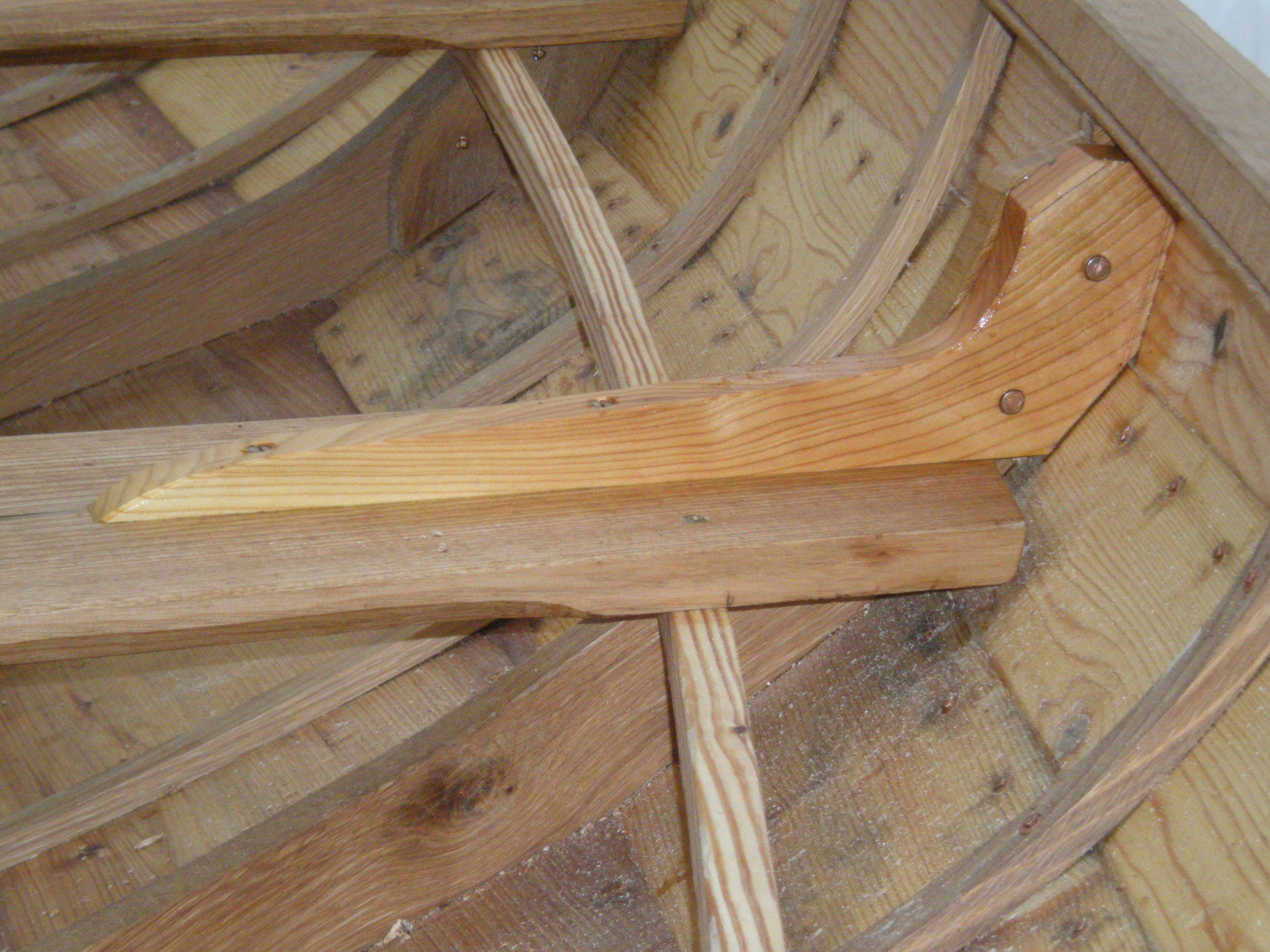
With the centerboard trunk in place, I had the mast step to do and then on to thwarts. I had butternut boards that would do nicely for thwarts but the mast step was a bit of a mystery as it was drawn centered over station 1 frame. Because of this placement the mast step needed to be thick, which made the depth from partner to step short and mast support minimal. Mower wrote that the class soon added partners at rail height, and we know that the boats were later decked, masts supported with shrouds and stays. I always liked the boat as designed, there is no longer intense class racing to consider, and these changes could come now as they did more than 110 years ago, if desired.
Looking at a 4 inch oak plank, I was attracted to a 3 inch round knot surrounded by it’s swirl of grain, and determined to use it as the mast step. Taking the chunk to my friend’s band saw I cut around the knot following the sweep of grain a few inches away from the knot. To deal with the frame in the way of the step, I cut the frames down and notched the step after the step bottom was given an arc to match the boat bottom and the knot drilled out to 3 inch diameter for the mast heel. After riveting through the step fore and aft of the step mortice, it was set in the frame notch and bolted into place with red lead on the mating surfaces.
standing knee
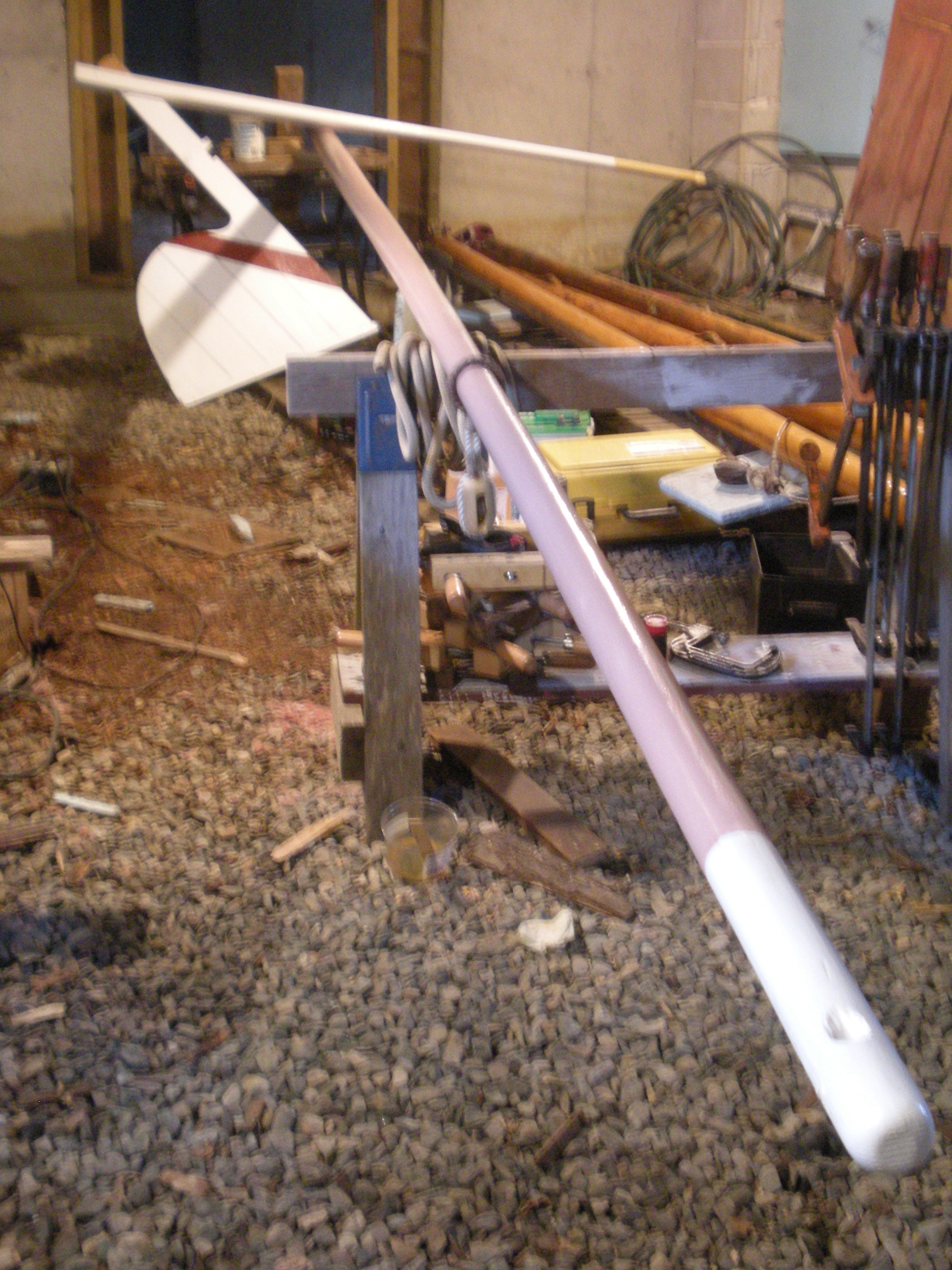
rudder and mast
Thwart width was marked on the risers fore and aft of the stations — ahead of the frame on one side, aft on the other. With measurements for each side of each thwart and from frame to frame, except on station 2 where the centerboard trunk intervened and the measurements went to the cedar above the trunk bottom, I cut the thwarts from the butternut boards. For added thwart support at stations 2 and 3 I screwed an oak 1” x 1” flush with the top of the trunk oak on both sides, extending aft of the trunk to go under station 3 thwart and forward for mast partner/trunk bracing. Fastening thwarts to risers with machine screws, the forward thwart had the 3 inch mast partner with oak doubling underneath all bolted through. Standing knees next.I made paper patterns of knee angles, laying flat paper edges on thwarts, folding the paper to the plank angle, and tracing the frame head on the paper. Then I looked through the knee collection a couple of times to come up with stock for six knees. I found one thick knee with a thick enough throat to get out all six knees. Taking that piece and the pattern to the bandsaw I made the rough division and resawed the smaller pieces, put them through the thickness planer, traced my patterns on them and cut them to shape. Back at the boat with some final trimming to fit they were ready to fasten in place. I riveted them to the frame heads and bolted longer arms through the thwarts.Applying raw linseed oil to everything over and over again before rolling her over for caulking, false bottom, false stem, and rudder hanging hardware, I had time to build the rudder and made the rudder hardware. After thinking about making the rudder bigger, as in the 1911 update, I stuck with the original design. I know a Swampscott dory I believe was Chaisson built with a rudder hung on a rod along the back center of the transom. With one gudgeon sliding down to the bottom of the rod, a second near the top, the top of the rod is pulled into a notch by a lanyard cleated inside the transom. Having rudder handling all at rail height is almost necessary with the severe rake of the Mower dory transom.
With one long oak board for the stock and three shorter pieces for the blade, I drilled through for two bolts and after it was bolted together put in a couple of drifts to pin loose ends. I planned to make a strap gudgeon the length of the rudder bottom. I got a silicon bronze strap, 3/16 inch by 1 inch. Red hot silicon bronze is maliable and ductile, and unlike other copper alloys a small area can be heated without heat conducting away from the heated spot also making handling possible. It takes Mapp gas or better. The bottom of the rudder is 26 inches long, so I heated the piece about 27 inches from one end on strap 6 feet long and started pounding it to round. Round was necessary because the angle between the bottom and the stock is less than 90 degrees. After a number of heatings I had a round gudgeon with full length straps. Rabbeting the rudder, I drilled and riveted through each of the rudder planks. Heating the remaining piece of strap, I bent it to be the top gudgeon. I also made the bottom fitting for the long pintle in this way using 5/16 by 1 1/2 inch bronze, bending a right angle with 5 inches to bolt to the transom heel and 1 1/2 inch projection which I bored and tapped for 3/8 inch rod.
false bottom installed

false stem bent on

hull painted, pintle bracket installed
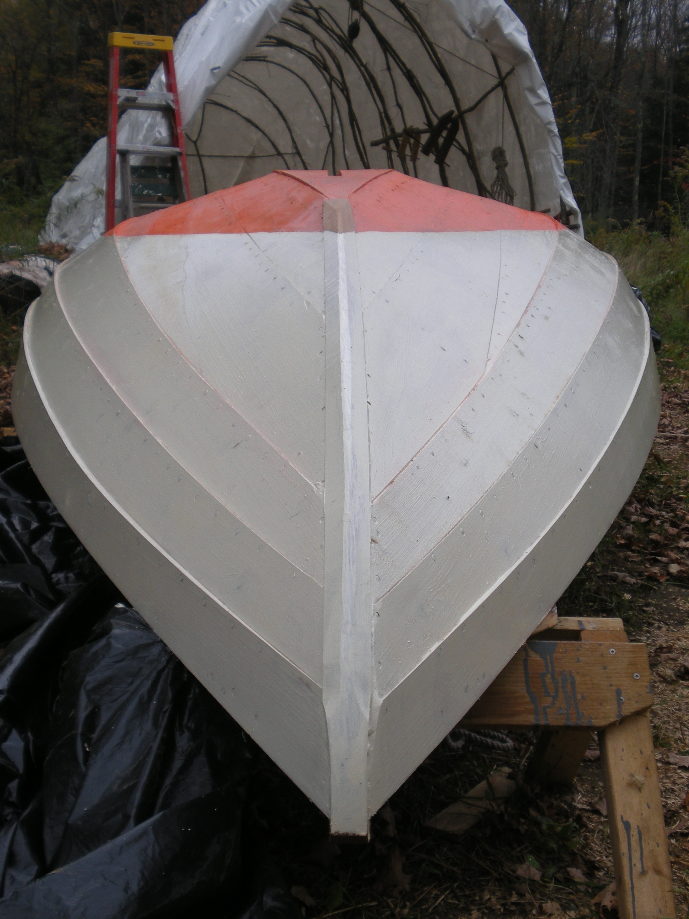
hull painted, cutwater formed
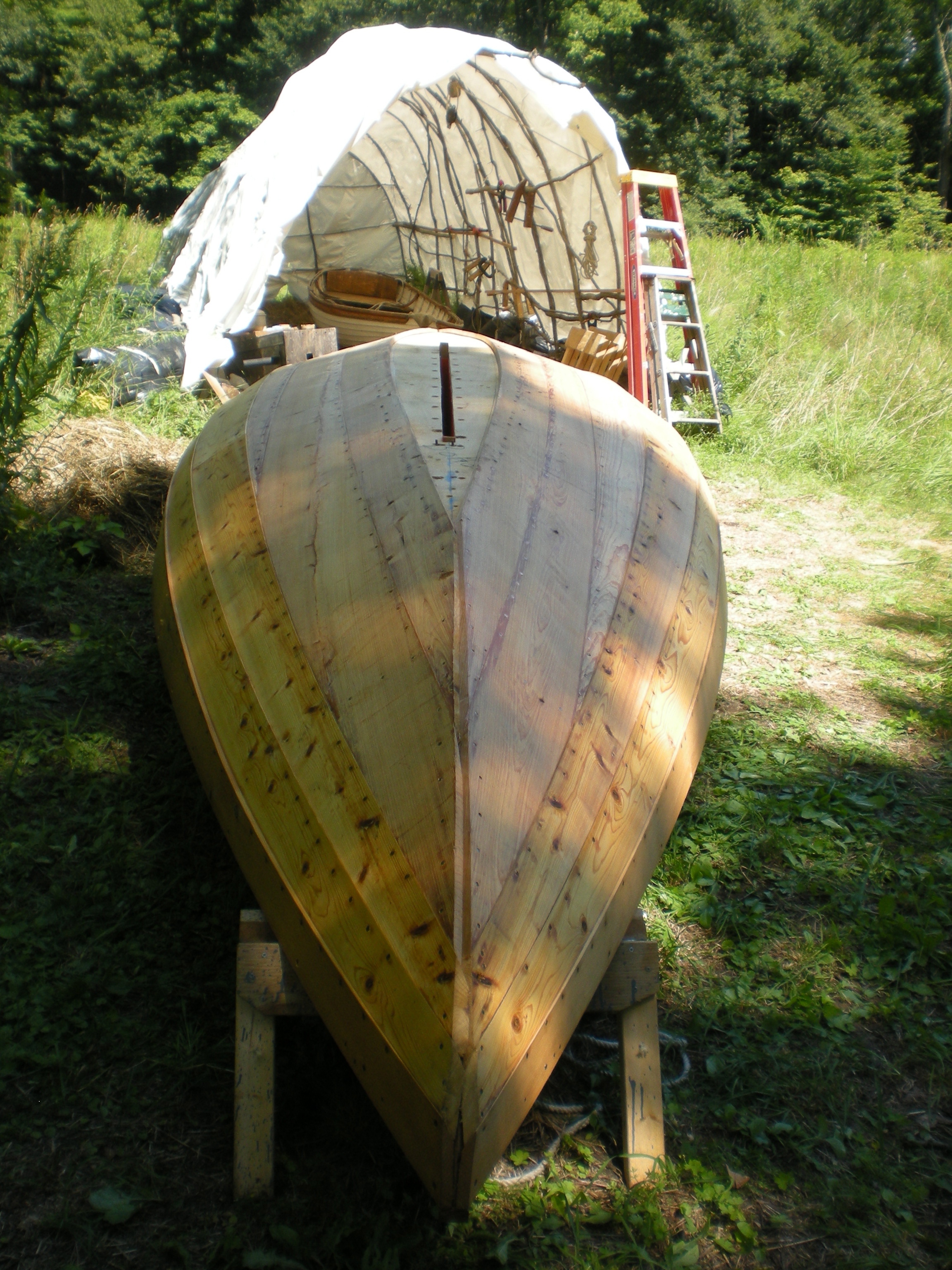
In the Rudder, possibly Mower’s, February 1900 description it sounds like false bottoms were installed as an afterthought because the boats would be shifted and sitting on the beach at Swampscott, between sailings. The design drawings shows a single bottom board and the lower garboard edges beveled flush. I planned on a false bottom and left the garboard edges square, the false bottom to fill the space and protect the garboard edges when taking the ground. Upside down facilitated planing plank ends flush with the transom and square across the stem. Caulking the garboard, transom and stem seams is normal in dory construction. A few of my dory lap seams seemed a little open and I rolled fine cotton wicking in them too. Painted with red lead the caulked seams were finished with seam compound and red leaded again after the compound set.
Getting one long oak board and a couple of shorter boards, and planing them for thickness, I was ready to fit the false bottom. With bottom rocker I had to hold the ends of the stock down to trace lines where it came down on the garboard. Cutting square to those lines, then beveling to match the angle between bottom and garboard edge, it took very little more trimming to get a good fit on the central piece. With this central piece held in place, I drew lines along it’s edges on the bottom board and also marked the station line location on the false bottom edges. Using these marks I located the centerboard trunk slot side to side on the false bottom board and fore and aft from the station lines. Drawn on the oak I cut the slot with circular saw and jig saw. Tried in place, it worked. Fitting the shorter pieces from my marked lines to the garboard on each side left me ready to fasten on the false bottom. All surfaces red leaded, I spread Dolfinite bedding compound over the bottom and held the center false bottom board in place with a frame wedged down from the sheer inwale. I fastened it with long screws into the stem foot, transom knee, and centerboard trunk, and shorter screws into but not through the pine bottom board. Then the side pieces were screwed in place.
While upside down I marked the ends for waterline, leveled the hull to those marks and side to side and marked all around for the painted waterline, using a laser level. I primed to the waterline with red lead. The bottom rudder hanging fitting was bolted through the bottom of the transom and through the transom knee. The stock for the false stem/cutwater was steamed and bent in place, after letting it stay clamped for more than a week to hold as much bend as possible it was bedded and fully fastened to the stem before trimming it’s cutwater shape. Then I painted the topsides white, two coats, with Albeck linseed oil paint. Before turning her back over the rudder hanging “pintle” rod was screwed into it’s fitting, peened for security, and the notched block for securing the top of the rod was screwed in place.
mast partner hinge
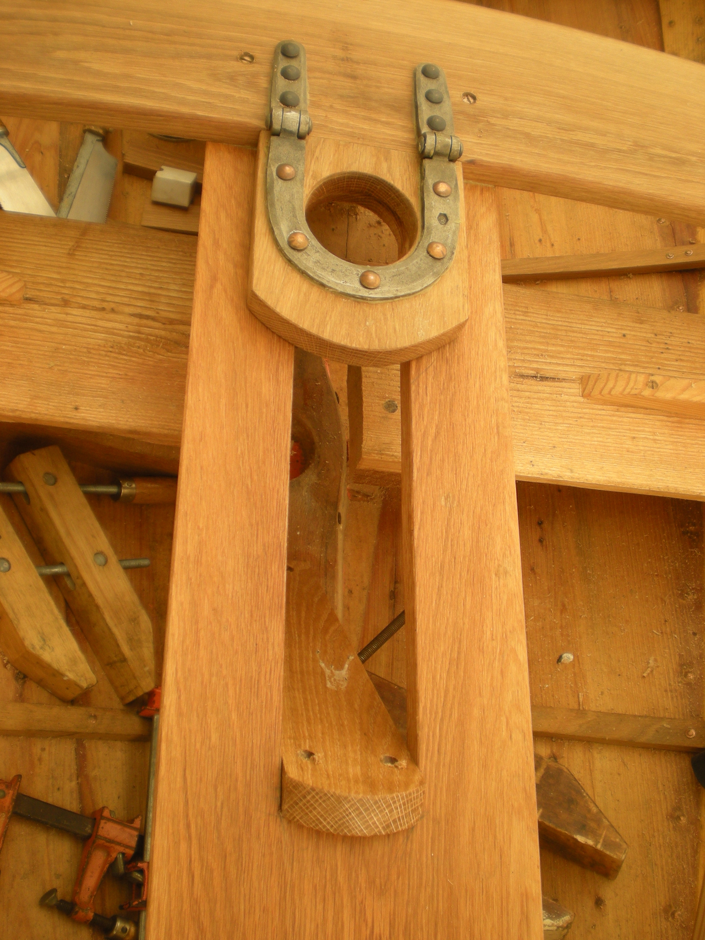
mast partner with heel slide
trunk cap and mast partner set up

stern sheets

floorboards coming
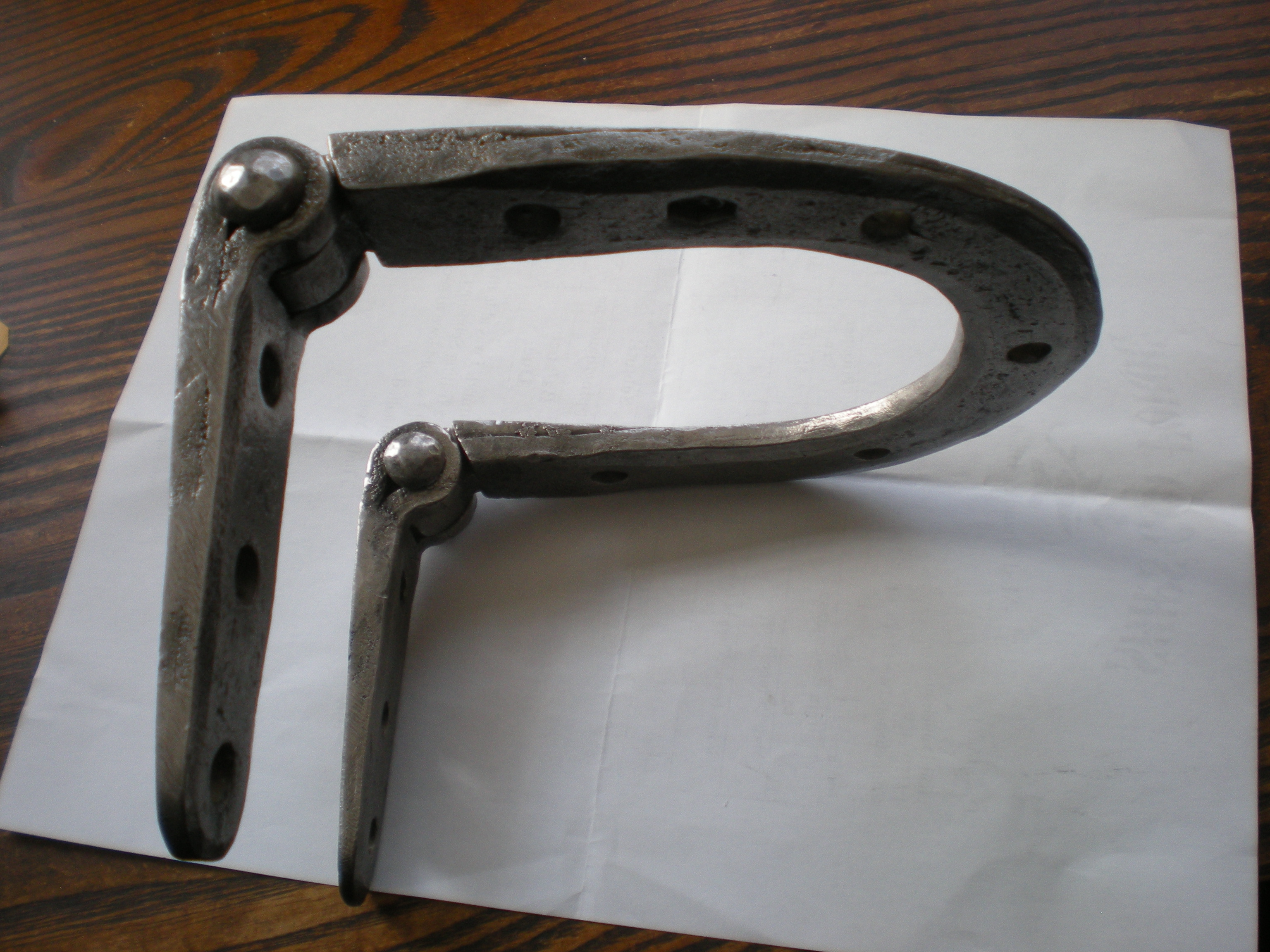
Before I started on my build our friend Hayden Brown, long in the sailmaking business, had got a copy of these plans from me and started building in his plywood and epoxy way. Now trying to catch up with me in finishing his build, he had also been saying I should stitch my own sails. Then he said he’d help me loft and lay out the sails. Meanwhile Hayden sent me the image of a whale boat mast partner hinge which looked just the thing to make single handed stepping possible. I sent the picture to Med Chandler, Ships Coy Forge in Lisbon, NH, who transformed links of old wrought iron schooner anchor chain into a beautiful mast partner hinge. With oak bent to a mold extending rail to rail and an oak board with slot fastened from trunk head ledge to a beam tying the heads of frame #1 together, and a board from the forward end of the slot to the mast step, the hinge was ready for use.
SAILING THE 1898 MOWER DORY
It would have been nice for the first sail to be off the beach at Swampscott, but I was determined to have her sailing as part of the John Gardner Small Craft Workshop during the WoodenBoat Show at Mystic Seaport Museum.

sail stitching
Roy Downs (Downs Sails, Danvers, MA) kindly ran the sail plan through his computer, which drew panel lines on the sailcloth, so a couple of weeks before the show I got three rolls of cloth, tape (sticky double sided and 3” cloth for the edges), webbing, rings, and thread. After cutting out the panels and setting up a makeshift bench for a growing sail more than 15’ from tack to leach, I started sticking panels together and torturing my sewing machine into stitching each seam twice. With one run to the repair shop to replace a broken drive belt, I got the mainsail done in a week. The jib took little more than a day to stitch, but roping the luff for halyard and downhaul was done only two days before leaving for the show, leaving just enough time to stitch up a long bag for the rig out of canvas scraps, lace main to spars, and load everything securely for the ride to Mystic.

wet at last
Meeting friends on arrival, help was at hand for launching at the public ramp just outside the Seaport. Steven Bauer got aboard to row around with me to dock at the JGSCW float and ooh how easy she moved under oars. I did find out the centerboard needed more weight, so the next day I drilled a hole in the trunk cap and wrangled a push stick to make sailing possible but slightly complicated for the need to push the board down with each tack. (Back from the show I cut a hole in t e centerboard and poured lead to weight it down.) My various crew never seemed to resent the task. Finally she was ready to sail! The mast partner hinge worked as it should, the sails were set and pulling. My brother was there waiting for his chance and two Traditional Small Craft Association (TSCA) men there from Cape Cod for the weekend answered the call for crew, off we went! The breeze was light, last of the NE before SW took over for the weekend, but she moved out easily as we headed over toward Sabino before the first tack and reach out past Lighthouse Point to tack again past square rigged Joseph Conrad and Gloucester fishing schooner L.A. Dunton to the Bulkhead and Pier lined with the show’s larger boats, tack away to sail up through the anchorage before turning back sailing along the channel, around the Seaport down toward Mystic’s road bridge to return to dock saying what a splendid first sail in a boat that hasn’t been built for 100 years. “You didn’t tell us this was the maiden voyage!” said one of our Cape Cod friends. “Lovely!”
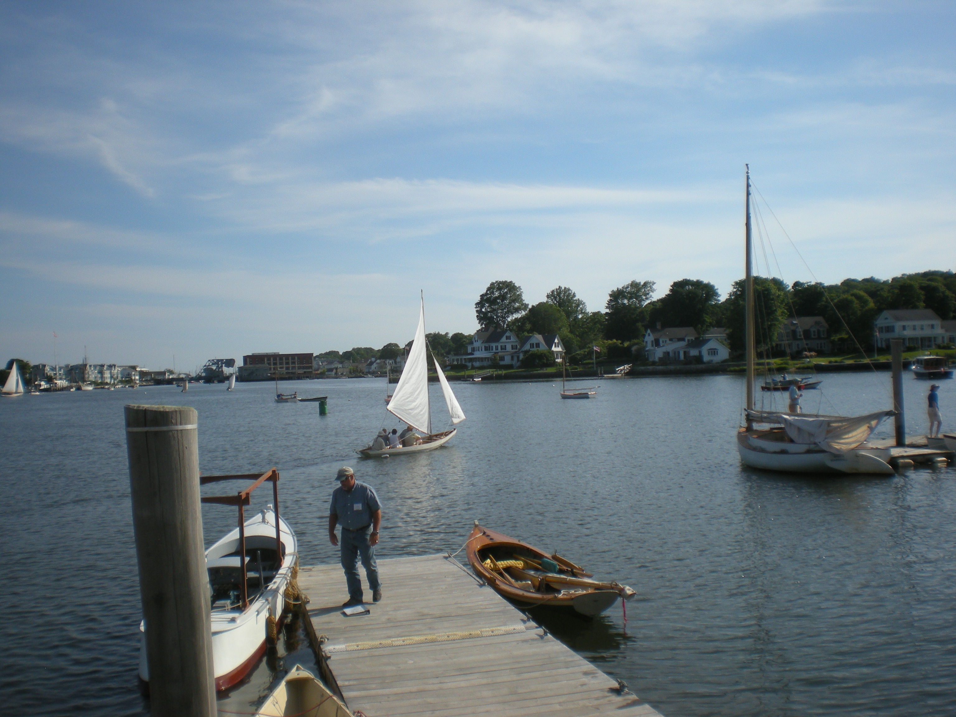
sailing at Mystic
sailing at Mystic

big sail down wind
Friday had started with me readying the dory and Grigg Millen inviting me to come along in his Hooper Island draketail for breakfast at the Mystic Marina down river. Miss Sue is such a sweetheart I didn’t resist, and breakfast took almost 2 hours. Then I had dealt with the centerboards push stick needs, so that was the only sail Friday but very like numerous sails the next two days as the breeze slowly got stronger. Saturday morning started with barely a whisper as the JGSCW crews started rowing up river. Mary Bauer had given her berth to the Cape Cod crew the day before and was ready for an early morning ghost and ghost we did on slight fluky NE air, out and about, turning slowly tack or jibe, around the show grounds, through the anchorage and back. Once, approaching the Point we almost stopped but mention of oars brought new life to our sails, ripples spreading off our bow again. We turned the Point, down to the bridge and back, slow and easy.
Sailed 4 or 5 more times Saturday with 3, 4 and 5 aboard, sometimes with people I knew, other times people who expressed an interest. I was fortunate to have the Cape Codders, Bob Lister and Bill Stirling, willing to come along when an experienced hand seemed a good idea. Sailing off the floats at the old Small Craft Workshops was always complicated with many boats coming in and out, now with the WoodenBoat Show happening too, traffic was constant and thick. Fortunately I had only one small collision as one of the Museum livery boats sailing out tacked as I jibed to go astern of them, instead leaving paint off the dory bow on their rail. Otherwise the dory did well with the dock a lee shore, jibing around to the float.
Saturday afternoon we rolled the dory onto the beach and I gave a little talk about the dory and it’s history before rolling her back for more sailing. Sunday started with another ride in Miss Sue, accompanying TSCA rowers and paddlers around Mason’s Island (a long SCW tradition), then it was back to sailing a few more times before the show ended. The wind had increased a bit more, but the dory handled it all well and with a final few tacks she brought up at the Museum Shipyard for hauling out. Joe Burke of Points East Magazine said she was the hit of the show, I don’t know if that was just his opinion or if he had heard talk. She satisfied me and seemed to for many others. Next I had to get her sailing out of Swampscott and Marblehead, her home waters.
Life can be complicated as well as fun, so it was not until the second weekend of August that the Mower dory saw salt water again. Months before I had signed on to sail in the Herreshoff cutter NELLIE in races off Marblehead and I meant to tow the dory down at that time. The following weekend was to be the 40th anniversary celebration at WoodenBoat where I also wanted to sail the dory. To make the long drive down east workable I called the daughter of a former neighbor who responded hoping that we would come. Excellent!
Unbeknownst to me after the WoodenBoat Show Joe Burke had put a notice in the August Points East magazine about the Mower dory at Mystic which brought on a call from the president of the Swampscott Club, Todd Mentuck, who I happened to have known for some time. He said August 9th (first day of NELLIE’s race weekend) the Swampscott Club was having it’s 115th anniversary party. I said I was coming down that weekend trailing the dory and would do what I could to get the boat there for the party.
Sometime in the next few days I did a little arithmetic placing the founding of the Swampscott Club at 1899, also the Mower dory’s first year. Actually the club had been informally in existance since 1893, but incorporated and with a fleet of racy 21’ dories 1899 was the official beginning. That was exciting! So driving down on the 8th I called Todd and said I could bring the dory over at 7 the next morning if there would be a secure space for it. Todd said he’d be there at 7 and have a space in front ready.
After an early breakfast, I re-rigged the mainsail so the club could fly it’s burgee from the mast and drove to Swampscott where I left the dory, mast up, burgee waving, in front of the club and drove back to Marblehead for the Corinthian Classic race. With a forecast of light sea breeze we instead sailed in 9 to 14 knots, excellent day for sailing. As soon as NELLIE was secure at the float I was off to Swampscott.
My friend Hayden Brown (luff tape manufacturer and sailmaker who insisted I stitch my own sails, getting Roy Downs’ help and also building his own ply/epoxy version of the Mower dory) called saying he was there with the boat and would wait for my arrival. He was there by the dory with Ed Chaisson, nephew of George L. Chaisson the Swampscott boat builder Ed described as “famous because he was the last”. John Gardner says he believed Elbridge Gerry Emmons built the 10 boats for the Swampscott Club, but here was Ed with blue prints of the 1898 Mower dory from his uncles shop. John Gardner does say that for 20 years after 1900 the Swampscott dory was the hottest racing boat around, distributed to the far Great Lakes. The Rudder article from 1900, which I’m told is clearly in the style of Thomas Fleming Day, magazine editor, says, “Beside the boats built for the Club a great many were turned out and sent to all parts of the country.” In these blueprints is evidence that Chaisson might have built some of these boats though his shop didn’t open until 10 years after the design first appeared.
That aside, Ed Chaisson and many Swampscott Club members gathered there eating and drinking at the club were thrilled to see the boat there, their boat. I was there to sail after going through the Club house and talking to a number of members. Hitched up, I backed down onto the beach where with help from a few club members we used the old Indian class system to get her off the trailer before rolling her into the rising tide. Ed wasn’t going to let the chance go by and climbed in with me. I hoisted the sails. Unfortunately for sailing, the earlier sea breeze had died away to rare gentle suggestions of air on which we drifted about in the mooring field, finally Hayden climbed aboard off the pier end float as we paddled to the beach. Must sail there another day. Ed said just being in that boat was the best thing ever for him except maybe when he got to sail in Constitution from Marblehead to Boston.
The following weekend WoodenBoat Magazine held it’e 40th anniversary celebration, inviting attendance from reader’s boats. We had been invited to stay with a friend up the road so after a day back home we drove off to Maine, towing trailer with dory. A little more than 8 hours later we were parked at our friends house. The next morning I drove the boat to WoodenBoat to see what was going on. Tours of the local boat builders were scheduled and tours of the WoodenBoat offices. With a site staked out for small boats, I parked the dory for the rest of the day, talking to people and looking around including a look around Brooklin Boat Yard.
We drove through rain all the way to Brooklin and that first morning was still stormy. The next morning I was ready to go sailing, the tide was out and coming in, Rich Hilsinger had said I could launch off their ramp, a light breeze ruffled Babson Harbor. All good. Ian Joseph had set up to show a couple of his boats and came down to help me get the boat off the trailer. After waiting for some kayakers to launch I backed the trailer onto the beach where Ian and I got her down onto the gravel waiting for the rising tide. The WB School waterfront manager came along saying they didn’t want people using the ramp, but when I said Rich had said I could, he thought a minute, then pointed out a mooring I could use and said he would put one of their dinghies on the mooring so I could come and go as I pleased. Better and better! thank you Greg and WB.
Anchor set in the rising tide it wasn’t long before she began to float. Pulling her out to the anchor and getting that aboard, I paddled to the mooring to ship the rudder and otherwise prepare to sail. With no crew here was a good chance to sail the racing dory alone. When I remembered to drop the centerboard the mooring field was in no more danger and we zipped back and forth, comfortably. From the first I have been impressed with the Mower dory’s stiffness, whether moving around in her moored or shifting weight to hold her upright. A gust bringing the rail close to the water, she straightens and accelerates as the sheet is eased. Coming back among the moored boats, astern of the NY 30 ALERA, I am hailed with the question “What is that design?”. “C. D. Mower 1898 21’ racing dory for the Swampscott Club.” “He sailed a few times in ALERA.” I headed up for a short gam which ended with the wish for a sail later, accepted. Thus I met Claas van der LInde.
After giving myself a tour of Brooklin Boatyard and a little lunch, I rowed out to the dory and saw ALERA’s dinghy coming my way. With a nice breeze blowing we sailed off past ALERA through Center Harbor, only bouncing the centerboard on a ledge once, tacking back down the Reach, Claas playing with the jib sheet lead for my edification and the dory’s improvement. The next day I spent much of the morning going over the Mower dory plans and story with Maynard Bray, Claas and Mike O’Brian, WB design editor, before finding Pat Lown, WB librarian and researcher who had been on that last short sail at Mystic, at the WB office ready to go for another sail. The wind was up considerably and gusty but with easing sheet we flew back and forth, a look into Naskeag Harbor and back through the anchorage off WoodenBoat.

Fantastic,As usual
Andrew
I have been researching the Chamberlain built 18′ Baybird class sailboat of 1916 that has been described as “the same length and model” as the Pleon Yacht Club decked boat that I have dated to at least 1915 if not before. I’d be interested in comparing research about the era with you.
Bruce Hammatt
rbhammatt@gmail.com
Spectacular! Well documented and beautifully built!
excellent report, fascinating, good design and workmanship, great photos help firing up the imagination. Thanks for your great work.
Thank you, Wolfgang.
What an inspiring post.
Do you have any plans to sell/publish the mower offsets for this dory.
The plans plus this post would make a great book/building guide.
Hello David, Thanks. I have the drawings and good copies of the drawings, also the offset table taken from the drawings. I have some more story on the Mower dory design that could make at least a little book. Not a bad idea. Cheers, Thad
I have pictures of a boat owned by my great grandfather in the early 20th century in Eagle Harbor, Michigan, described as a “21′ racing dory.” I was trying to learn more about it and found your story. The plan in The Rudder looks a lot like my pictures. I was thinking if it’s a racing dory, maybe he raced with others in a class of boats on the UP, but now I’m wondering if his boat was photographed because it was such a novelty up there. Thanks for the great article and the clue that this might be a Mower dory.
Hello David,
Great! I believe E G Emmens in Swmpscott, MA, built many of the Mower dories an shipped them all over the country. After the plans were updated in 1911, they could be built by anyone as the plans were available and easily followed by a knowledgeable builder. It would be interesting to know just when that boat was built.
Thanks for continuing the story!